Complete installation walkthrough for the Growatt MIN series single-phase inverters. Wall mounting, DC/AC wiring, grounding, commissioning, and ShinePhone setup.
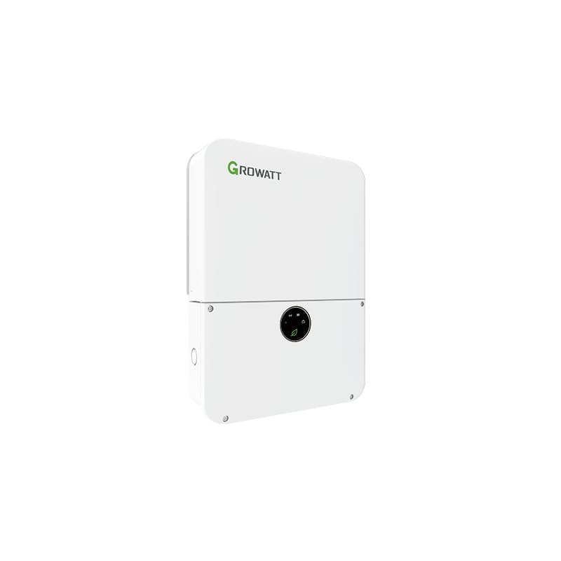
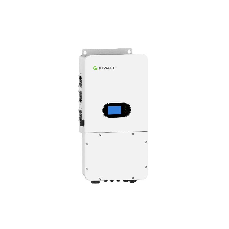
The Growatt MIN family covers most residential rooftops between 2.5 kW and 11.4 kW. This guide walks a qualified electrician through a real install of the MIN 2500-6000TL-X X2 Pro (grid-tie) and the MIN 2500-6000TL-XH (hybrid) — the two MIN variants we ship most across the GCC, Africa, and Europe. The same workflow applies to the smaller MIN 2500-5000TL-XA and the larger MIN 7000-10000TL-X / MIN 3000-11400TL-XH-US.
1. Tools, Materials, and Documents
- Growatt MIN inverter with factory wall bracket and mounting kit
- PV array with MC4 connectors — see model-specific MPPT voltage windows (typically 80–550 V DC for X2 Pro, 80–560 V DC for XH)
- For hybrid (XH) only: LiFePO4 battery such as Growatt ARK HV 3.75–12.5 kWh stack with BAT-BOX and the matching CAN/RS485 communication cable
- ShineWiFi-X, ShineWiFi-S, ShineLAN-X, or 4G ShineLink dongle for monitoring
- DC isolator rated ≥ 600 V (the X2 Pro has an integrated DC switch — still required upstream in some jurisdictions)
- AC breaker: 16 A for ≤ 3 kW, 25 A for 3.6–5 kW, 32 A for 6 kW (single-phase, Type C, 30 mA RCD Type A or B per local code)
- PV string cable: 4 mm² double-insulated solar-rated
- AC mains cable: 4 mm² for ≤ 5 kW, 6 mm² for 6 kW runs over 10 m
- Earth conductor: 6 mm² minimum, bonded to the building MET
- Torque wrench (1.0–25 Nm range), Phoenix-style screwdriver set, MC4 crimper and unlocking key
- Inverter installation manual and DNO/utility approval (DEWA Shams Dubai, SEWA, ADDC, etc.)
2. Choosing the Mounting Location
The MIN housing is IP65, so outdoor mounting is allowed, but real-world thermal derating still applies. Pick a north or shaded wall — never west-facing — and respect these clearances printed on page 18 of the manual:
- 500 mm clear above the inverter (heat plume)
- 300 mm on each side
- 500 mm below for cable bending radius
- 600 mm in front for service access
Wall must support 4× the inverter weight. The MIN 6000TL-X weighs 18.5 kg; the larger MIN 10000TL-X is 26 kg. Concrete, solid brick, or steel C-channel only — hollow plasterboard is not acceptable.
3. Wall Mounting the Bracket
- Mark the four bracket holes using the supplied paper template. Bracket bottom edge sits at chest height (1.5 m floor-to-bracket).
- Drill Ø10 mm × 60 mm deep holes for the M8 expansion anchors supplied in the kit.
- Insert the anchors, fit the bracket, and torque the M8 bolts to 16 Nm.
- Lift the inverter onto the bracket — the rear lip slots over the bracket hook. Two technicians for any unit above MIN 6000TL.
- Secure the inverter to the bracket with the bottom anti-theft screw (M5, 2 Nm).
4. DC (PV) String Wiring
The MIN 2500-6000TL-X X2 Pro has two independent MPPTs, each rated 13 A. The MIN 7000-10000TL-X has two MPPTs at 16 A each. Confirm string sizing before wiring:
- Calculate open-circuit voltage at the coldest expected ambient: Voc(string) = N × Voc(panel) × (1 + β × ΔT). Result must stay under 550 V DC for X2 Pro / XH and 1000 V DC for the 10000TL-X.
- Verify Isc(string) ≤ MPPT current rating. A typical 8-panel string of 550 W Tier-1 modules sits around 14 A — within spec for the 10000TL-X but at the limit for the 6000TL.
- Cover the panels with an opaque tarp before wiring to keep open-circuit voltage at zero.
- Crimp MC4 connectors with a calibrated tool — bad crimps are the #1 cause of warranty returns.
- Plug positive into PV+ and negative into PV− for each MPPT. Listen for the audible click.
- Flip the integrated DC switch on the X2 Pro to OFF until full commissioning.
5. AC Grid Wiring
- Open the AC terminal cover (4 screws, Pozidriv #2).
- Strip the AC cable jacket back 80 mm and individual cores 15 mm.
- Land L1 on "L", N on "N", PE on the earth lug. Torque the AC screw terminals to 1.8 Nm.
- Refit the cover with the cable gland sealed (the gland must compress around the cable to maintain IP65).
- At the distribution board: install a dedicated 2-pole MCB (Type C) plus an RCD/RCBO matched to local code. Many EU markets now require a Type B RCD for transformerless inverters.
6. Battery Wiring (Hybrid XH Only)
For the MIN 2500-6000TL-XH or XH2, connect a Growatt ARK HV battery stack:
- Mount the BAT-BOX base on a level concrete floor — never on carpet or wood.
- Stack 3 to 8 ARK HV modules (3.75 kWh each) and click the inter-module connectors.
- Run the orange BAT+ and black BAT− cables to the inverter battery terminals. Torque to 4 Nm.
- Connect the BMS CAN cable from the BAT-BOX to the COM port labelled "BMS" on the inverter.
- Power on the battery breaker only after the inverter is fully wired.
7. Grounding and Earth Bonding
The MIN chassis has an external M6 earth stud next to the AC gland. Run a 6 mm² green/yellow conductor from this stud directly to the main earthing terminal. Do not chain through the AC PE — the manual requires a separate equipotential bond. Verify earth continuity with a loop tester (target < 0.5 Ω).
8. Communications Dongle Installation
- Locate the USB-style COM port on the underside of the inverter.
- Insert the ShineWiFi-X (or ShineLAN-X for wired Ethernet) and twist the locking ring clockwise.
- The dongle LED blinks red until paired. Pairing happens during commissioning (see Step 10).
9. First Power-Up
- Energise the AC breaker first. The inverter LCD initialises and shows "Waiting".
- Flip the DC switch to ON. Within 30 seconds you should see PV voltage on the screen.
- Verify the LED status indicator turns solid green — the inverter is exporting.
- If the unit shows "PV Voltage Low" (typical morning condition) wait until irradiance exceeds 80 V on the MPPT.
10. Commissioning via ShinePhone
- Install ShinePhone from the App Store or Google Play and register an account.
- Tap "+", then "WiFi Configuration". Connect your phone to the inverter's "Growatt-XXXX" hotspot (default password
12345678). - Select your home 2.4 GHz SSID (5 GHz is not supported), enter the password, and submit.
- Within 2 minutes the ShineWiFi LED turns solid blue. The inverter now appears under "My Plant".
- Set country code, grid type (TN-S, TT, IT), and date/time. For hybrid units, configure battery type (Lithium / Lead-acid) and SOC limits (10–100% recommended).
- For time-of-use markets, programme the charge/discharge windows under "Battery → Schedule".
Common Installer Mistakes
- Reversed DC polarity: the MIN will display "PV Reverse" and refuse to start — swap MC4s rather than forcing the input.
- Loose AC torque: under 1.5 Nm the terminals overheat under load. Use a calibrated wrench.
- 5 GHz only router: ShineWiFi cannot pair. Enable 2.4 GHz on the same SSID.
- No external DC isolator: required in AU, DE, UK regardless of the integrated switch.
- Hybrid with no BMS comm cable: the battery will appear in the menu but never charge.
Handover Checklist
- Photograph all torque-marked terminals
- Print the ShinePhone plant link and email it to the homeowner
- Leave the manual and the warranty card on site
- Submit the witness-test paperwork to the DNO/utility within 7 days
Frequently Asked Questions
What size cable do I need for a Growatt MIN 6000TL-X?
Does the Growatt MIN X2 Pro have a built-in DC isolator?
What torque setting do I use on the AC terminals?
Can I pair the ShineWiFi dongle with a 5 GHz network?
How long does a full Growatt MIN install take?
Do I need DNO/utility approval before I energise the inverter?
What battery is compatible with the Growatt MIN-XH?
Ready for a personalized quote?
WhatsApp us — average reply time under 15 minutes.